Dreamcast Repair
The journey of a thousand parts.
Image Source: lordsofgaming.net
Editor's Note: This article was originally published on Feb. 4, 2025
I’ve always admired the Sega Dreamcast. From the contemporary fascination with the style of Jet Set Radio (See: Bomb Rush Cyberfunk), to the insane jazz fusion soundtrack of Sonic Adventure, to the unique atmosphere and sprawling world of Shenmue, to the strange wonder of Seaman, to the recent breakthroughs in porting GTA3 to the system, the Dreamcast has many quirks to admire.
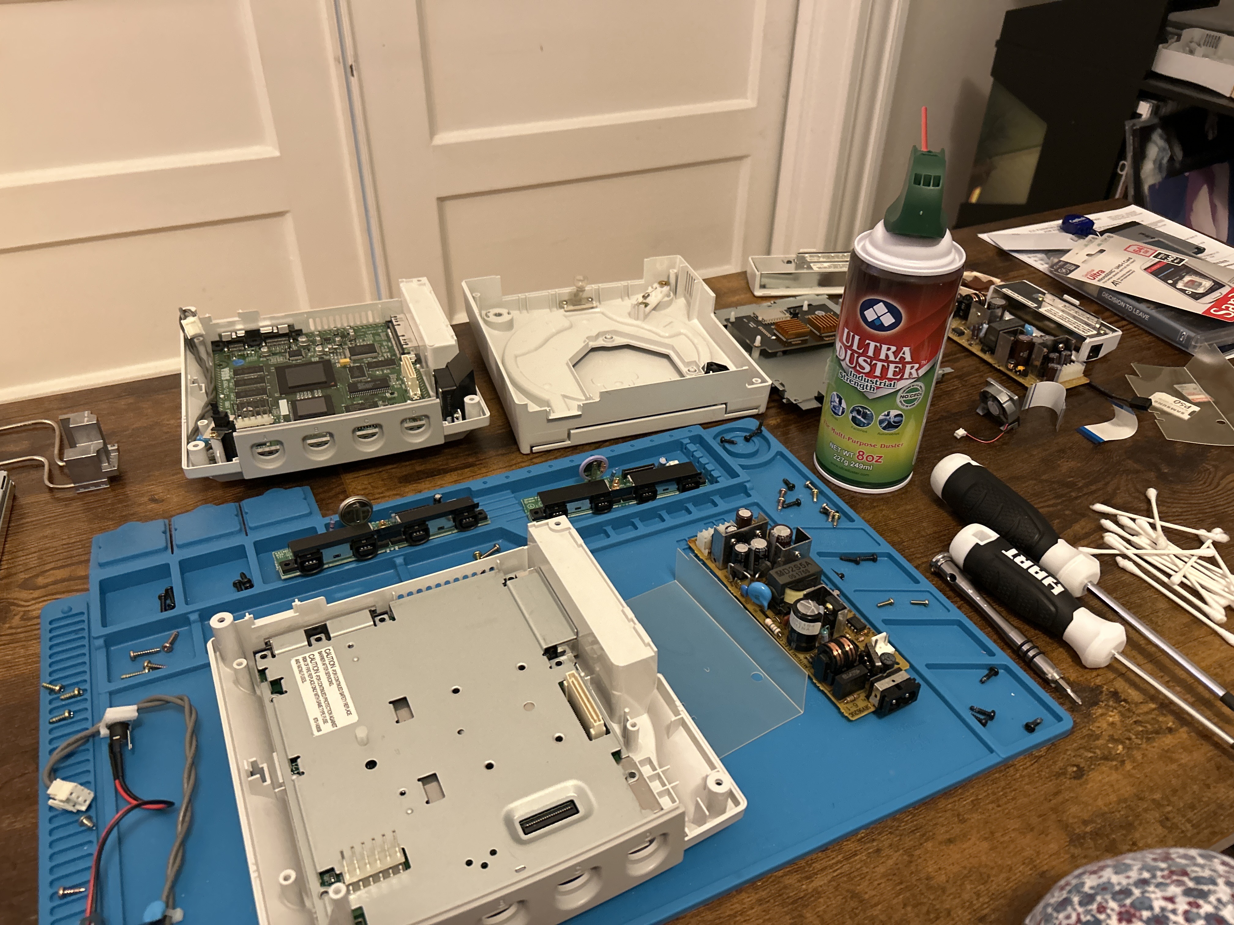
Now, I’ve repaired a few consoles in my time. Despite this, what started as a simple cleaning turned into a multi-week affair quickly. The teardown is a straightforward process, as shown on the Game Tech Wiki. After performing a deep wash of the outer shell and plastic bits, followed with an alcohol scrub for the electrical ones, I got her plugged in and ready to see if she would POST. I power her on and… the fan starts spinning! Yet, there is no video output. After some troubleshooting and digging online, I came across this thread. My heart sank. I wasn’t certain that when putting the device back together that I used the exact screws in their exact original location. From here, I had to take the walk of shame to tear her down again, and sure enough… I fumbled. There are two different screws used to hold the dreamcast together. The first set is used to hold together the motherboard and RF shield to the housing as well as the housing to itself. The second set is used to hold the GD-ROM to the motherboard. Set #1 includes both 10 mm and 12mm screws, the 10 being a silver color and the 12 black. Set #2, as evidenced by the poor quality of readily available documentation online, contain ??? mm screws, of ??? color. TO SET THE RECORD STRAIGHT: YOU NEED TO USE THE 10mm SILVER SCREWS FOR ALL POINTS ON THE GD-ROM. Failure to do so will result in destroying the trace from the GPU to the video output on your motherboard. That 2mm difference just so happens to be slightly more clearance than granted to you by the RF shield. So, if you use the 12mm screw, and tighten it, you drive it DIRECTLY INTO THE MOTHERBOARD; the screws are the same width, there is nothing stopping you. As shown in the tear down from IFIXIT (often a reputable source, mind you), the GD-ROM Starts with a BLACK screw on the left slot and ends with NO screw on the left slot of the GD-ROM at all. The occurrence of destroying motherboard traces in this way is so common that the sample image on Wikipedia shows a board with a destroyed trace. With newfound knowledge in hand, to eBay I went for replacement parts.
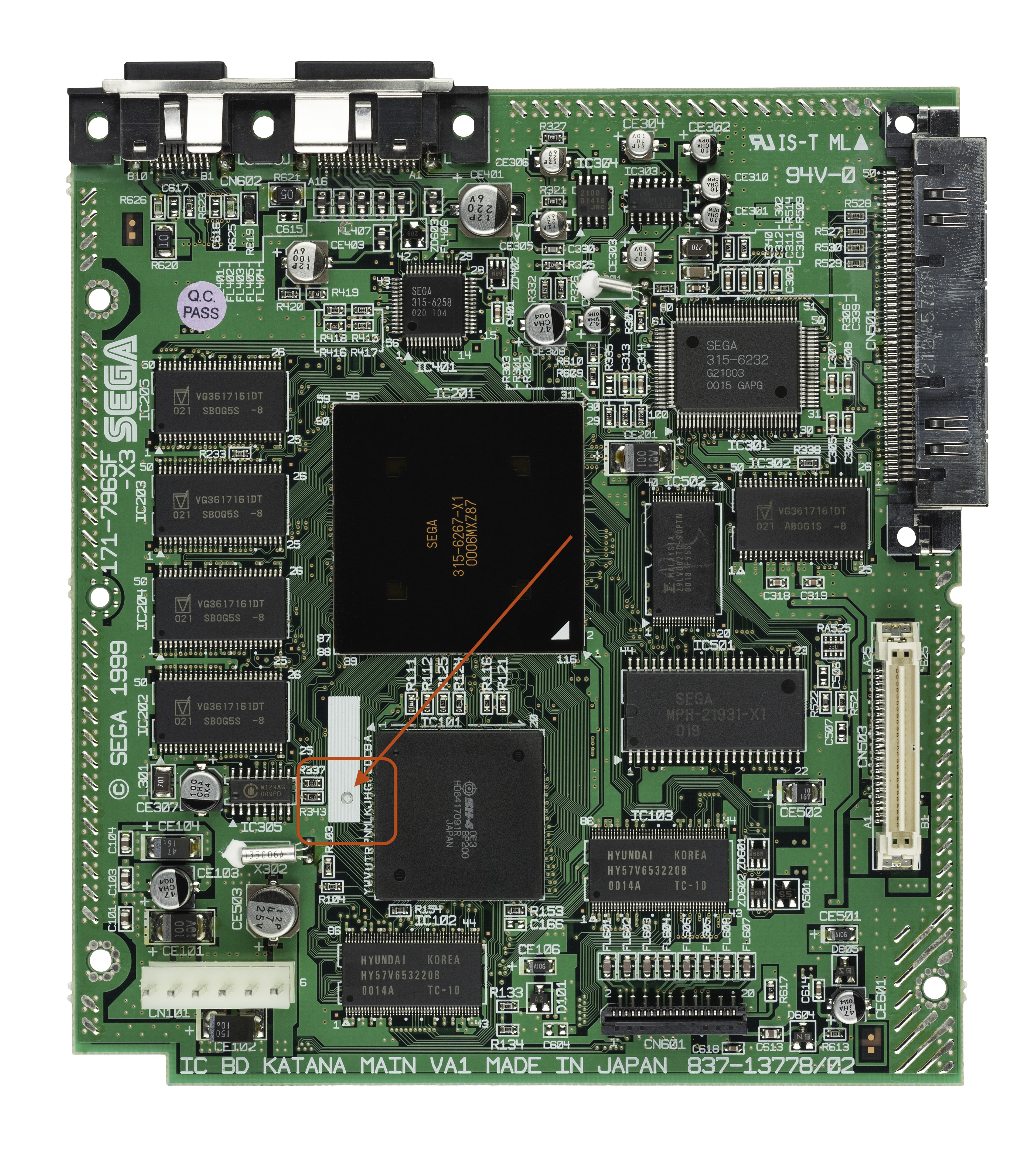
Since I destroyed my motherboard (R.I.P), I began my search for a replacement. Now, this is where the distinction between Dreamcast hardware revisions comes into play. There are three models of the console: VA0 (98-99), VA1 (99-00), and VA2 (Oct. 00 - Dec. 00). The model I was working with was a VA0. Unfortunately, eBay returned no results for any working VA0 motherboards. Through searching, I found that the motherboard’s design between the VA1 and VA0 stayed very consistent, with just some minor changes (foreshadowing) in heat sink design. Since VA1’s are more common, there were luckily some listings on eBay for the VA1 motherboard. A key difference between the VA1 and VA0 boards, however, is in the GD-ROM interface. The VA0 drive is powered by 5v and the VA1 by 3.3v. So, alongside the motherboard, I picked up a VA1 GD-ROM drive. Putting the pieces together was relatively straight forward, aside from the fan connector. Since this connector was different, that meant that without proper power to the fan, the machine would not POST! To make matters worse. The controller port for the VA0 and VA1 Dreamcasts have different pinouts, so despite using the same ribbon cable, the devices CAN NOT INTERFACE CORRECTLY.
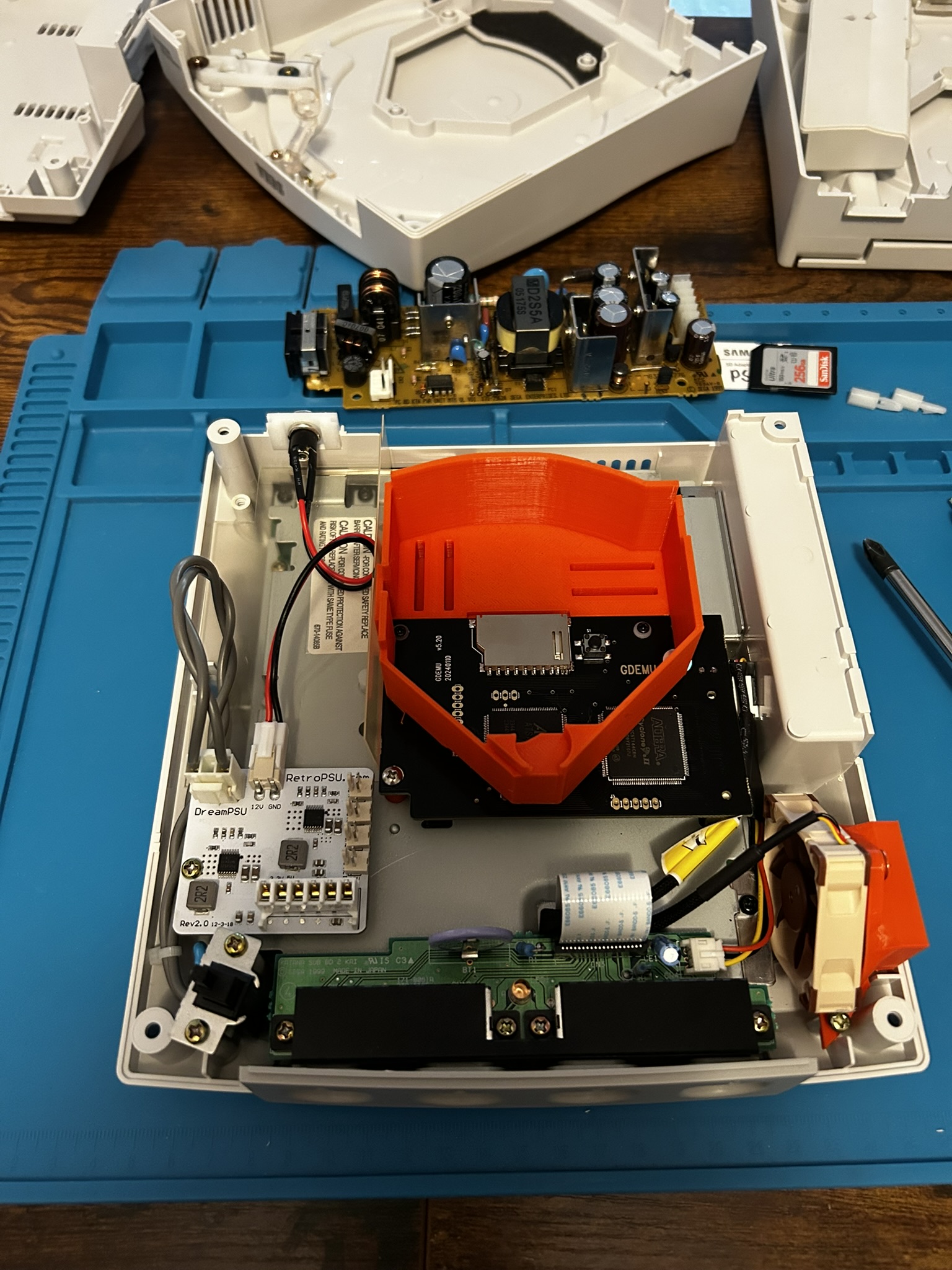
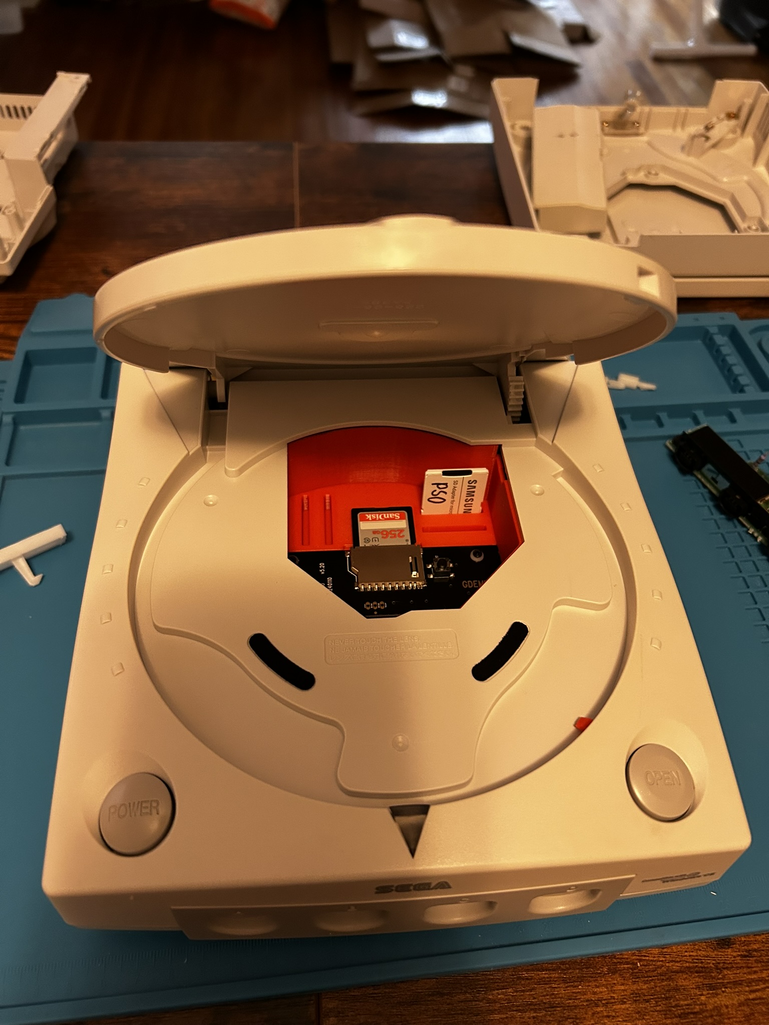
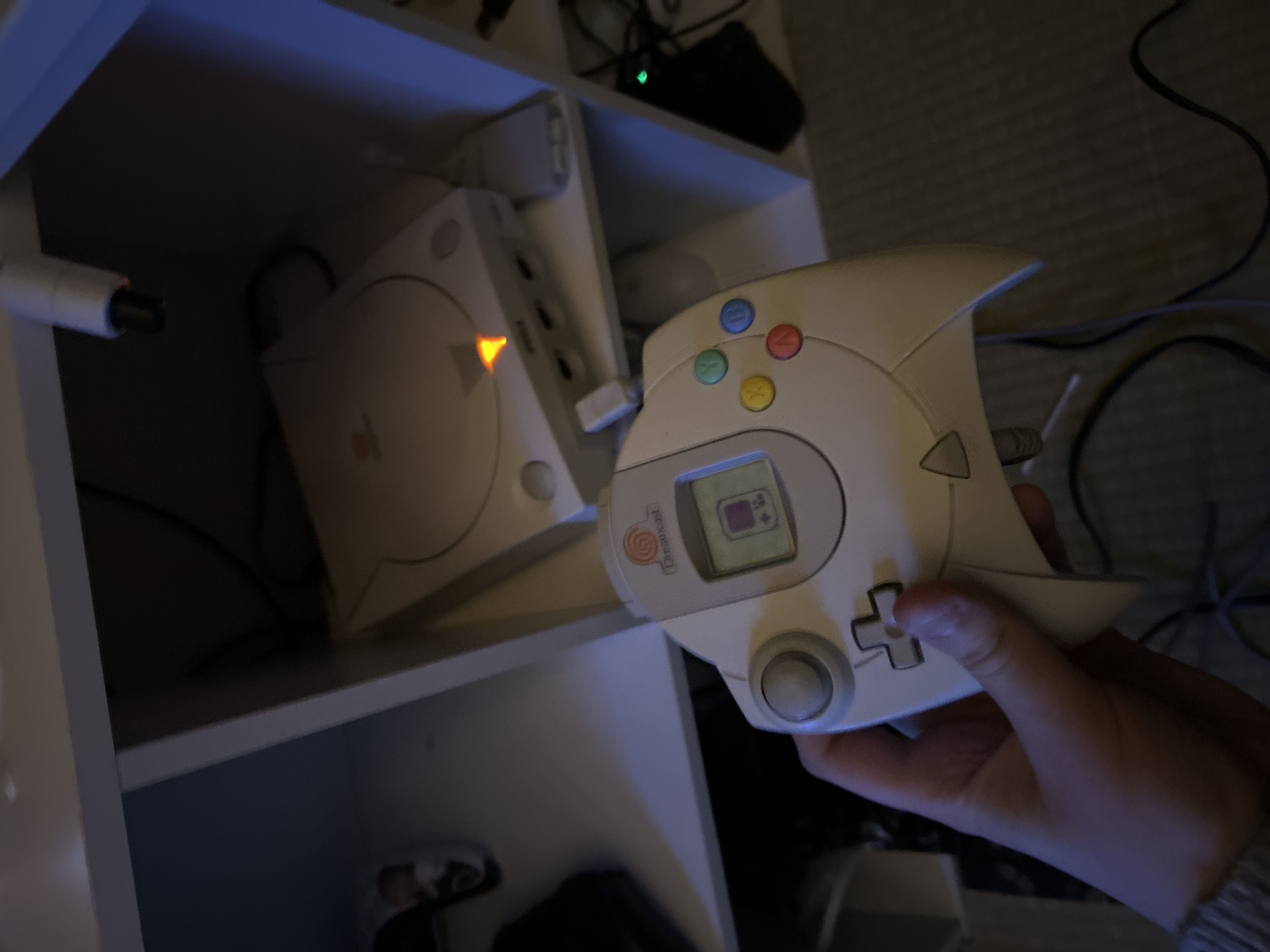
By the time all was said and done, I ended up going through: 3 motherboards, 3 outer shells, 3 GD-ROM Drives, 3 RF shields, and 2 controller ports (in addition to all the other miscellaneous parts). Alongside the VA1 Dreamcast, I installed the following mods: A GD-EMU, A Noctua Fan + Bracket, and A Dream PSU. While certainly a headache, I'd do it all again (and probably will again in the future).
- GD-EMU - A GD-ROM replacement that allows for booting games from an SD card.
- Noctua Fan mod - Improves thermal performance of the Dreamcast.
- Dream PSU - Removes some of the overbearing capacitors, further improving thermals and streamline power delivery.
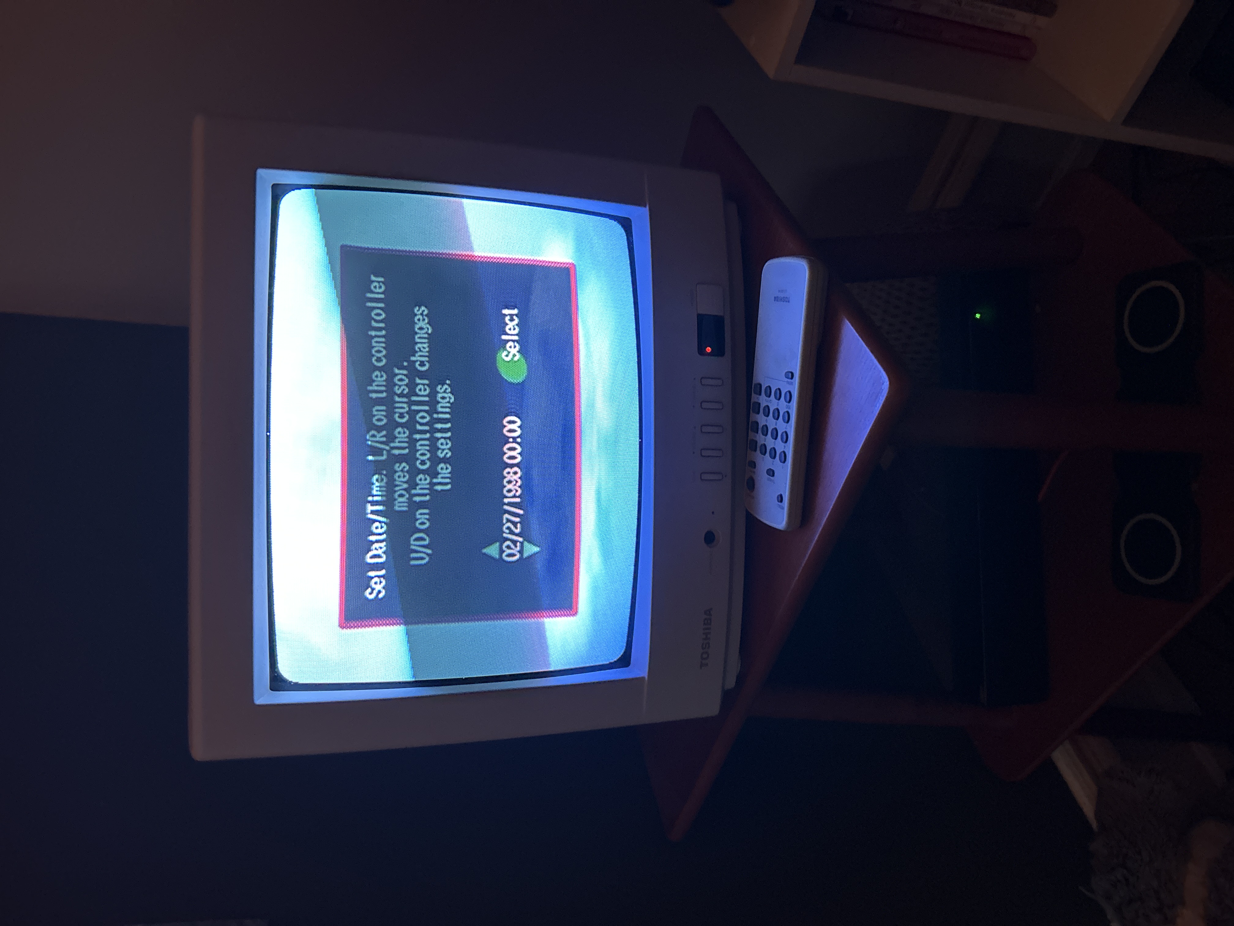
Below are the results!
Gallery